
DIY Garage Door Opener with ESP8266 Module and RPi
Published on: January 9, 2020
Happy 2020! Welcome to the 13th Raspberry Pi Tutorial! Thought I'd do something a little different today and just show a demo in the video below and write out the steps to the actual project here and on GitHub.
You can find the code and more detailed technical information in the following GitHub repo: https://github.com/naztronaut/NodeMCU-Pi-Garage-Control
Here's a quick demo of what the end product looks like:
Let's talk hardware:

You'll need the following pieces of hardware for this project (get more info in the Github repo):
- ESP8266 - I use a NodeMCU since it makes a lot of things pretty easy)
- (optional) Raspberry Pi - any will work for this project (for web app if you're using it) - Not pictured above
- 5v Relay module
- DHT11 Sensor (or any humidity/temperature sensor)
- Jumber Cables
- Project box to store everything
Now for Software:
- ESPHome - perhaps through Hassio
- MQTT Broker - any will work. I use Mosquitto installed on my Hassio (which is in turn installed on a Raspberry Pi 4)
- (optional) Apache for the web server -Check out the following tutorial for more info: Run Apache on your Pi
Now let's connect everything as shown in this fritz schematic:
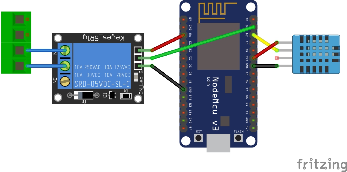
| Color | Pin | Connects To |
|---|---|---|
| Red (relay) | VU | VIN on Relay |
| Black (relay) | Any Ground Pin | GND on Relay |
| Green | D1 | Data pin on Relay |
| Blue | Normally Open and Common pins on relay | To garage door controller |
| Red (DHT) | any 3v Pin On NodeMCU | Power on DHT Module |
| Black (DHT) | Any Ground Pin on NodeMCU | GND on DHT Module |
| Yellow | D2 | Data Pin on DHT |
You can switch the D1, D2, power, and ground pins as you see fit. But I believe there is just one VU pin for the Red relay cable on the NodeMCU. The VU offers USB power (5v) which is required to power the relay. Connecting it to VIN or 3V will not work.
My garage door opener comes with 4 terminals. The two left-most terminals are to control the door. And the next two are the safety sensors which I left alone. The green 4-pin thing in the diagram is just a representation of what my connection looks like, yours may be different! Look up your brand and see where your connections should go.
If you do change the data pins, make sure you edit the YAML to reflect your changes!
ESPHome makes it really easy to configure the ESP modules. You can find the complete YAML file here: https://github.com/naztronaut/NodeMCU-Pi-Garage-Control/blob/master/esphome/garage.yaml
Let's do a quick breakdown of what we have in our YAML. First we create a Switch:
switch:
  - platform: gpio
    pin:
      number: D1
      inverted: yes
    name: "Garage Door"
    id: garageDoor
  - platform: template
    name: "Garage Door Switch"
    id: garageDoorTemplate
    icon: "mdi:garage"
    turn_on_action:
    - switch.turn_on: garageDoor
    - delay: 1s
    - switch.turn_off: garageDoor
Our switch GPIO Pin Number is D1 with an id of garageDoor so that we can reference it later. We create a quick template which will let us simulate a button click, which is turn on the garageDoor for 1 second and then turn it back off. Pretty simple! I recommend reading more about the switch component on the ESPHome website: https://esphome.io/components/switch/gpio.html
Next we have our MQTT configuration which we use to trigger our Garage Door.
mqtt:
  broker: {{Broker IP}}
  discovery: True
  username: "your mqtt username"
  password: "your mqtt password"
  topic_prefix: "garage"
  on_message:
    topic: "garageDoor/trigger"
    then:
      - switch.turn_on: garageDoorTemplate
You will need some kind of MQTT broker. There are some cloud ones avaialble. I use the Mosquitto plugin available to me by Hassio: https://www.home-assistant.io/addons/mosquitto/
We subscribe to garageDoor/trigger and once we receive anything, we trigger the garageDoorTemplate.
Next we have our DHT11 sensor. Again, I recommed reading the DHT section of ESPHome: https://esphome.io/components/sensor/dht.html
sensor:
  - platform: dht
    model: DHT11
    pin: D2
    temperature:
      name: "Garage Temperature"
      id: garageTemp
      state_topic: "garage/temperature"
      filters:
      - lambda: return x * (9.0/5.0) + 32.0;
      unit_of_measurement: "°F"
    humidity:
      name: "Garage Humidity"
      id: garageHumidity
      state_topic: "garage/humidity"
    update_interval: 10s
The sensor updates every 10 seconds for me and displays the temperatures in Fahrenheit. And it automatically publishes the temperature and humidity data to topics garage/temperature and garage/humidity to which I subscribe to from the web app. You can also subscribe to this from any MQTT client that can talk to your broker.
Once everything is connected, you can trigger the garage door with any MQTT client that can talk to your broker. For the webapp, I implement MQTT.js (https://github.com/mqttjs/MQTT.js) which I found to be extremely useful and intuitive. I'm using a very small part of the library so be sure to check them out to learn more.
One quick note: If you chnage any of the MQTT Topics above, whether it's the temperature/humidity publish topic or garage door trigger topic, make sure you update the appropiate line in script.js, otherwise the app won't receive/publish data to the broker properly.
TODO:
There's currently no way to tell if the door is open or closed without actually looking at the door. I plan on enhancing this application with a a reed switch which will help me determine if it's open or closed. Expect either an update to this post or a supplemental post at a future date.
Have questions about the tutorial? Ask below, I welcome all questions and comments.
Remember to checkout the Resources section below for associated downloadable content, JSFiddle links, and other resources. Watch the video and follow along!
Resources:
Check out the entire project on GitHub: https://github.com/naztronaut/NodeMCU-Pi-Garage-Control